(!)Due to Microsoft's end of support for Internet Explorer 11 on 15/06/2022, this site does not support the recommended environment.
- Our website upgrade are completed! Latest improvements are now LIVE to enhance your ordering experience. You may be logged out due to the update. Please take note to login again or reset credentials if needed. More details here.
Level indicator (float sensor type) (LF-E)

Click this image to zoom it.
Move the mouse over the image to zoom
- Volume Discount
[Features]
• Detects changes to the liquid surface from floats.
• Allows for easy switching between NO (normally open) and NC (normally closed).
• Magnetic components are not used in floats so it is best to use tanks with messy liquids (water, oil, cooling oil) in them.
• Can be used regardless of liquid conductivity.
• Plug direction can be changed through the combination of connector and contact holder.
• Degree of protection: IP65 compliant
Part Number
Configured Part Number is shown.
Drawing

Product Specification
| Material | Operating temperature | Maximum voltage | Maximum Current | Contact Capacity | Connector | Cable conductor cross-sectional area | |||
|---|---|---|---|---|---|---|---|---|---|
| Main body | O-ring | Magnet | Protection Rating | Thread size | |||||
| polyamide Gray | Nitrile Rubber (NBR) | Alnico magnet | Max. 80°C Min. -20°C | DC230V | 2A | 40VA | IP65 | PG9 (for cable outer diameter ⌀6–8) PG11 (for cable outer diameter ⌀8–10) | max. 1.5 mm2 |
Specifications Table

Note: Cut the gauge and adjust it to your desired length.
Usage Example

How to Adjust the Length of the Gauge

- Remove the float from the gauge.
- The gauge has scales for oil and water specifications marked on the front and back, respectively, and these indicate L1.
- Cut the gauge at the scale for the liquid level position you want to detect. Cutting can be easily done with nippers, etc.
- When cutting at your desired scale, the insertion length of the float has been taken into account.
- Finally, insert the float into the gauge.
Connection method

*: The customer must provide separately.
2. Remove the packing from the connector, take out the contact holder, and loosen the plug.
3. Pass the cable through the plug and connector, and connect it to terminals 1 and 2 of the contact holder.
(No other connections are necessary.)
4. Return the contact holder to its original position in the connector, attach the packing, mount it to the main unit,
and tighten the screw.
5. Once you tighten the plug, the wiring connection to the indicator is complete.
[NO] [NC] Switching Method
![Level indicator (float sensor type) (LF-E) [NO] [NC] Switching Method Diagram](http://content.misumi-ec.com/image/upload/t_msmwm_wyg/v1/p/jp/product/wysiwyg/221005484107/221005484107_004_20230801115855.jpg)
| Part Number |
|---|
| LF-250E |
| LF-360E |
| Part Number | Standard Unit Price | Minimum order quantity | Volume Discount | Days to Ship | RoHS | Parallel Screw for Pipes Pilot Hole Diameter (mm) | Connection screw G | Main Body Mounting and Liquid Surface Distance (Minimum to Maximum) (mm) |
|---|---|---|---|---|---|---|---|---|
MYR 586.15 | 1 Piece(s) | Available | 9 Day(s) | 10 | 24.5 | G 3/4 | 75~250 | |
MYR 562.29 | 1 Piece(s) | Available | 9 Day(s) or more | 10 | 30.6 | G 1 | 85~360 |
Loading...
Basic Information
| Type | Long type | Long type category | I type | Main body material | Polyamide |
|---|---|---|---|---|---|
| Seal Part Material | NBR | Maximum operating temperature(℃) | 80 | Additional function for level visibility | Sensor / Float |

Specification/Dimensions
-
Parallel Screw for Pipes Pilot Hole Diameter(mm)
- 24.5
- 30.6
-
Connection screw G
- G 1
- G 3/4
-
Main Body Mounting and Liquid Surface Distance (Minimum to Maximum)(mm)
- 75~250
- 85~360
-
type
- LF-250
- LF-360
-
CAD
- 2D
- 3D
Days to Ship
-
- All
- 9 Day(s) or Less
Specify Alterations
- The specifications and dimensions of some parts may not be fully covered. For exact details, refer to manufacturer catalogs .
Additional Products in this Category
- Breather Cap (BN-38S)
- Level Indicator (LR-C, LT-C)
- Steel cover type breather cap, steel cover type pressure cap
- Nut (Parallel Threads For Pipes)
- Sensor for CLR (Column-Type Level Indicator)
- Breather Cap (No level gauge)
- Oil plug (with/without ventilation holes)
- Oil Window (Star type)
Customers Who Viewed This Item Also Viewed
-
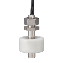
 Float Switches - Horizontal / Vertical Type
MISUMI
Standard Price : MYR 1,017.61-
Days to Ship : 9 Day(s) or more
-
-

-
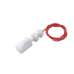
![Capacitive Proximity Sensor for Liquid Level Detection [E2K-L]](//my.misumi-ec.com/linked/material/mech/OMR1/PHOTO/IMG_WIN_E2K-L_DS_J_1_1.jpg?$product_recommend_b$) Capacitive Proximity Sensor for Liquid Level Detection [E2K-L]
Capacitive Proximity Sensor for Liquid Level Detection [E2K-L]OMRON
Standard Price : MYR 936.37-
Days to Ship : 5 Day(s) or more
-
-


![Capacitive Proximity Sensor for Liquid Level Detection [E2K-L]](http://my.misumi-ec.com/linked/material/mech/OMR1/PHOTO/IMG_WIN_E2K-L_DS_J_1_1.jpg?$product_recommend_b$)
Tech Support
- Factory Automation, Electronics, Tools, & MRO (Maintenance, Repair and Operations)
- Tel:(60) 3 7890 6399
- 9:00am - 6:00pm (Monday - Friday)
9:00am - 1:00pm (Saturday) - Technical Inquiry
- Credit Card
- Bank Transfer


Social Media
MISUMI Contact
Copyright © MISUMI Corporation All Rights Reserved.
How can we improve?
How can we improve?
While we are not able to respond directly to comments submitted in this form, the information will be reviewed for future improvement.
Customer Privacy Policy
Thank you for your cooperation.
While we are not able to respond directly to comments submitted in this form, the information will be reviewed for future improvement.
Please use the inquiry form.
Customer Privacy Policy