(!)Due to Microsoft's end of support for Internet Explorer 11 on 15/06/2022, this site does not support the recommended environment.
- Our website upgrade are completed! Latest improvements are now LIVE to enhance your ordering experience. You may be logged out due to the update. Please take note to login again or reset credentials if needed. More details here.
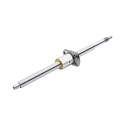
Rolled Ball Screws Shaft Dia.10 Lead 2/4 Accuracy Grade C7


- Economy
- Rolled Ball Screws Shaft Dia.10 Lead 2/4 Accuracy Grade C7 from MISUMI.
- The Rolled Ball Screws have a shaft diameter of 10 mm and are available in two different lead sizes: 2mm or 4mm.
- The accuracy grade option for this product is C7.
- The overall length of the shaft screw can be customized to fit a range of configurations, from 150mm to 600mm, in 1mm increments.
- The lead twisting direction for this product is right-handed.
- The screw shaft is made of S55C while the nut is made of SCM420.
- RoHS
Part Number
Configured Part Number is shown.
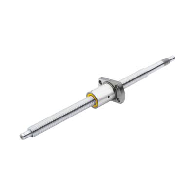
Economy Rolled Ball Screws Shaft Dia. 10
- High-precision C7 accuracy grade for reliable performance.
- Customizable shaft lengths within a specified range in 1mm increments
- Shaft made from durable S55C material for enhanced longevity.
- Right-handed lead twist for efficient operation.
- Nut made from SCM420 material for high strength and wear resistance.


MISUMI Standard

Cheaper Price

Product Variety

3D CAD Support

・Eliminate drawing processing and save design time; ships as fast as 6 days after ordering

■Quality Assurance
・Even for MISUMI Economy series, pre-shipment quality inspections are conducted just like MISUMI Standard products to provide items that meet catalog specifications


| Accuracy Grade | Screw Dia. | Lead | Screw Shaft | Nut | ||||
 Material Material |  Hardness Hardness |  Surface Treatment Surface Treatment | Material | Hardness | Surface Treatment | |||
| C7 | 10 | 2·4 | S55C Equivalent | Induction Hardening 58~62HRC | - | SCM420 Equivalent | Carburized 58~62HRC | - |
(Unit: mm)


| Part Number |  Total Screw Shaft Length L Total Screw Shaft Length L(1mm increments) | Y | Number of Circuits | Basic Load Rating | Axial Clearance | Twisting Direction | Screw Shaft Support Unit (Sold Separately) | |||||
 Type Type |  Screw Shaft O.D. Screw Shaft O.D. |  Lead Lead | C (Dynamic) kN | C (Static) kN | Shape | Fixed Side Model | Support Side Model | |||||
| C-TBSE | 10 | 02 | 150~600 | L-53 | 3 Turns | 1.2 | 2.1 | 0.05 or less | Right | Square Type | C-TEK8 | C-TEF8 |
| Round Type | C-TFK8 | C-TFF6 | ||||||||||
| Short Type | E-TLK8S | E-TLF8 | ||||||||||
| 04 | 1.6 | 3.4 | Square Type | C-TEK8 | C-TEF8 | |||||||
| Round Type | C-TFK8 | C-TFF6 | ||||||||||
| Short Type | E-TLK8S | E-TLF8 | ||||||||||
| *The Y dimension must be greater than the total length of the nut | kgf=N×0.101972 | |||||||||||
| Lead Accuracy | Maximum Tolerance for Screw Shaft Runout (See table below for details) | ||
| Unit: mm | |||
| MISUMI Economy series | C7 | 0.350 | |
| MISUMI Standard product | 0.150 | ||

| Screw Shaft Length | |||||
| ~200 | 201~315 | 316~400 | 401~500 | 501~630 | |
| MISUMI Economy series | 0.120 | 0.160 | 0.210 | 0.270 | 0.350 |
| MISUMI Standard | 0.065 | 0.080 | 0.100 | 0.120 | 0.150 |

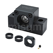
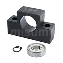
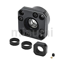
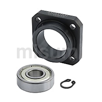
| Economy Series Support Units - Standard Square Type | Economy Series Support Units - Round Type | ||
| Fixed Side Model | Supported Side Model | Fixed Side Model | Supported Side Model |
 |  |  |  |
●Rotating the nut by hand may not feel smooth, but does not affect the positioning accuracy, so this product is suitable for multi-point positioning feeding mechanism. Please feel free to use.
●If low runout is required during operation (e.g., machining equipment), please use MISUMI Standard products.
●During operation, if excessive noise or sharp, piercing sounds occur, please be sure to confirm the installation accuracy of the screw and whether the specifications of peripheral components such as motors and couplings are appropriate. MISUMI does not guarantee the noise level after the screw is assembled.
●Although lithium soap-based grease is applied at the factory, new grease should be injected every 2 to 3 months after receipt as a standard, otherwise performance will be affected.
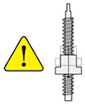
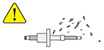
●Do not allow the nut to exceed the ball screw nut travel range or screw it off the screw shaft, as this will cause balls to fall out and damage ball circulation parts.
●Please note that placing the ball screw and nut at an incline may cause them to fall due to their own weight.
●This product is a machined type, so there will be knife patterns and color difference in its appearance. Small scratches or color changes without affecting the use and main function are of a normal phenomenon. Please feel free to use.
■Precautions for Design and Assembly of Ball Screws and Peripheral Parts
A ball screw is a component that only bears axial loads. If it is subjected to radial loads or moment loads, it may lead to poor sliding, vibration, and abnormal noise, thereby shortening the service life.
The causes of radial and moment loads on ball screws are axial deviation and parallelism errors of surrounding components. Therefore, to prevent errors, peripheral parts of the ball screw must be correctly designed and assembled.
●Axial misalignment between the ball screw and the support unit assembly (Fig. 1)
-Axial deviation refers to the deviation between the axis of the ball screw fixed by the fixed-side support unit and the axis of the bearing in the supported-side support unit.
-Allowable axial deviation value: 20μ or less (reference value)
●Parallelism between the ball screw and the linear guide (Fig. 2)
-Parallelism error refers to the vertical or horizontal tilt of the ball screw relative to a reference such as a linear guide.
-Allowable tilt value: 1/2000 or less (Fig. 3)
●Precautions during Assembly
If abnormal noise is detected during ball screw operation or if sticking occurs during movement after assembly, please loosen the connections of each component to adjust, and reassemble after smooth movement is achieved.
-Error in the horizontal direction of the support unit (Fig. 1)
-Parallelism error between the linear guide and the ball screw (Fig. 2)
-Fixing of the worktable and the nut bracket
-Fixing of the ball screw nut and the nut bracket





| Accuracy Grade | Screw Dia. | Lead | Screw Shaft | Nut | ||||
| Material | Hardness | Surface Treatment | Material | Hardness | Surface Treatment | |||
| C7 | 10 | 2·4 | S55C Equivalent | Induction Hardening 58~62HRC | - | SCM420 Equivalent | Carburized 58~62HRC | - |
(Unit: mm)
| Part Number | ④ Total Screw Shaft Length L (1mm increments) | Y | Number of Circuits | Basic Load Rating | Axial Clearance | Twisting Direction | Screw Shaft Support Unit (Sold Separately) | |||||
| ①Type | ② Screw Shaft O.D. | ③ Lead | C (Dynamic) kN | C (Static) kN | Shape | Fixed Side Model | Support Side Model | |||||
| C-TBSE | 10 | 02 | 150~600 | L-53 | 3 Turns | 1.2 | 2.1 | 0.05 or less | Right | Square Type | C-TEK8 | C-TEF8 |
| Round Type | C-TFK8 | C-TFF6 | ||||||||||
| Short Type | E-TLK8S | E-TLF8 | ||||||||||
| 04 | 1.6 | 3.4 | Square Type | C-TEK8 | C-TEF8 | |||||||
| Round Type | C-TFK8 | C-TFF6 | ||||||||||
| Short Type | E-TLK8S | E-TLF8 | ||||||||||
| *The Y dimension must be greater than the total length of the nut | kgf=N×0.101972 | |||||||||||
| Alterations | Code | Spec. |
① No machining on support side shaft end | NC | No machining added on the support side shaft end. Ordering Code NC |
② Changes the nut direction | RLC | Changes the nut direction. Ordering Code RLC |
③ No machining of support side shaft end retaining ring groove | RNC | No machining of support side shaft end retaining ring groove. Ordering Code RNC |
④ Change the length of the support side shaft end | FC | Changes the length of the support side shaft end. 10≤FC≤20 FC = 1mm increments Ordering Code FC20 |
| Alterations | Code | Spec. |
⑤ Machining of wrench flats on fixed side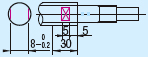 Incomplete hardened area | SZC | Adds wrench flats on the fixed side shaft end. Ordering Code SZC  Ball bearings will fall out if the ball nut crosses the wrench flatsThe nut may not be able to move to the incomplete hardening range; please be careful when selecting. Ball bearings will fall out if the ball nut crosses the wrench flatsThe nut may not be able to move to the incomplete hardening range; please be careful when selecting. |
| ⑥ Machining of keyways on fixed side shaft end Detailed dimensions of the keyway  P.1 P.1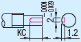 | KC | Adds a keyway on the fixed side shaft end. 2≤KC≤8 When specified simultaneously with ⑩,2≤KC≤F-1  Not applicable for P=5 Not applicable for P=5KC = 1mm increments Ordering Code KC5 |
⑦ Machining of keyways on fixed side shaft end | KLC | The position of the fixed side shaft end keyway machining can be specified. (Keyway dimensions are the same as KC.) 2≤K≤7 K+S≤8 When specified simultaneously with ⑩,2≤K≤16 K+S≤F-1 K>b(Keyway width) Not applicable for P=5K, S = 1mm increments Ordering Code KLC-K5-S2 |
⑧ Machining of flat on fixed side shaft end | SC | Adds a flat on the fixed side shaft end. 5≤SC≤8 When specified simultaneously with ⑩,5≤SC≤F-1 SC = 1mm increments Ordering Code SC7 |
⑨ No machining of small steps on the fixed side | NF | No machining of small steps on the fixed side Ordering Code NF |
| ⑩ Change Fixed-side Small Step Dimensions Recommended  | FP | Changes the fixed side small step dimensions 9≤F≤18 5≤P≤6 F, P = 1mm increments Ordering Code FP-F18-P6 |
| ⑪ Change Fixed-side Large Step Dimensions Recommended  | EU | Changes the fixed side large step dimensions 11≤E≤35 8≤U≤E-3 E, U = 1mm increments Ordering Code EU-E35-U10 |
⑫ No machining of fixed side large step male thread | NU | No machining of fixed side large step male thread Ordering Code NU |
Only one of ①, ③, or ④ can be selected.Only one of ⑥, ⑦, or ⑧ can be selected.⑨ and ⑩ cannot be specified simultaneously.When ⑪ and ⑫ are specified simultaneously, the external thread will not be machined regardless of the value specified for U in ⑪.When ⑪ or ⑫ is specified, the recommended support units may not be usable; please reconfirm.When any alteration is specified, the nut travel range (Y dimension) may become shorter; please ensure the nut travel range is greater than the total nut length.
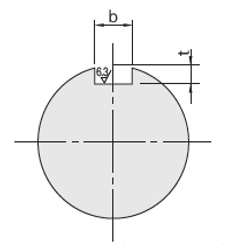
| Shaft Dia. | b | t | ||
| Reference Dimension | Tolerance (N9) | Reference Dimension | Tolerance | |
| 6~7 | 2 | -0.004 -0.029 | 1.2 | +0.1 0 |
| 8~10 | 3 | 1.8 | ||
| 11~12 | 4 | 0 -0.03 | 2.5 | |
| 13~17 | 5 | 3.0 | ||
| 18~20 | 6 | 3.5 | ||
| Lead Accuracy | Maximum Tolerance for Screw Shaft Runout (See table below for details) | ||
| Unit: mm | |||
| MISUMI Economy series | C7 | 0.350 | |
| MISUMI Standard product | 0.150 | ||
Screw Shaft Runout Tolerance
| Screw Shaft Length | |||||
| ~200 | 201~315 | 316~400 | 401~500 | 501~630 | |
| MISUMI Economy series | 0.120 | 0.160 | 0.210 | 0.270 | 0.350 |
| MISUMI Standard | 0.065 | 0.080 | 0.100 | 0.120 | 0.150 |

The figures below show the noise levels of ball screws with different specifications.
Note:
- The figures below are ball screws noise levels by specification.
- Results are for reference and may not cover all spectification.
- MISUMI C7 grade ensures under 70 dB at 1500 RPM.
(noise measured 1 meter from the ball screws)

Part Number
CAD Data download and 3D preview are not available because the part number has not yet been determined.
- *In order to open the CAD Data download and 3D preview screen, the part number must be fixed.
- Please confirm the part number from "Specification / Dimension"on the left side, and then perform the CAD Data Download / 3D Preview operation.
Basic Information
| Screw Shaft O.D.(Ø) | 10 | Type | Rolled | Accuracy Grade | C7 |
|---|---|---|---|---|---|
| Flange Shape Details | Round, 2 Sides Cut Flat | Shaft End Type | EK Type | Fixed Side of Square Bearing Assembly (Purchase Separately) | C-TEK8 |
| Square Support Component Support Side (Purchase Separately) | C-TEF8 | Fixed Side of Round Bearing Assembly (Purchase Separately) | C-TFK8 | Support Side of Circular Support Assembly (Purchase Separately) | C-TFF6 |

- The specifications and dimensions of some parts may not be fully covered. For exact details, refer to manufacturer catalogs .
Frequently asked question (FAQ)
- Question: What is the operating temperature limit for the economy series rolled ball screw?
- Answer: The operating temperature limit for the economy series rolled ball screw is 80°. Exceeding this limit will cause damage to the circulating parts and seals, as well as the deformation of the screw shaft and nut, affecting the life.
- Question: How to do if there is abnormal noise heard in use?
- Answer: MISUMI does not guarantee there is no abnormal noise during use. If abnormal noise occurs, please check the installation accuracy and the correct selection of surrounding parts. Please loosen the parts before re-adjustment. Please refer to "Precautions" for details.
- Question: Is it normal to feel stuck when rotating the nut by hand?
- Answer: It is a normal phenomenon, because this product is a rolled ball screw, and there is no run-and-fit test before leaving the factory. The sticking will disappear after running for a period of time under the condition of ensuring the installation accuracy If the sticking reaches the point where the motor can not drive, please contact MISUMI.
Additional Products in this Category
- Precision Ball Screws Compact Nut - Shaft Dia. 6, 8, Lead 1, 2 - Accuracy Grade C3, C5, C7
- Support Units Peripherals - Stoppers for Ball Screws
- Left and Right Hand Precision Ball Screws - Shaft Dia. 10; Lead 2 / 4 / 10 - Accuracy Grade C5
- Precision Ball Screws Shaft Dia.40 Lead 5/10/20/40 Precision Grade C5
- Rolled Ball Screw, Non-Preloading Type (Nut Single Unit) BLK
- Rolling ball screw, no-preload type (nut body), CNF
- Rolling ball screw BTK-V type overall length 1 mm specification, supports shaft edged processing
- Precision ball screw BNK type (large lead) overall length 1 mm specification, supports shaft edged processing
Tech Support
- Credit Card
- Bank Transfer



Social Media
MISUMI Contact
Copyright © MISUMI Corporation All Rights Reserved.
How can we improve?
How can we improve?
While we are not able to respond directly to comments submitted in this form, the information will be reviewed for future improvement.
Customer Privacy Policy
Thank you for your cooperation.
While we are not able to respond directly to comments submitted in this form, the information will be reviewed for future improvement.
Please use the inquiry form.
Customer Privacy Policy