(!)Due to Microsoft's end of support for Internet Explorer 11 on 15/06/2022, this site does not support the recommended environment.
- Our website upgrade are completed! Latest improvements are now LIVE to enhance your ordering experience. You may be logged out due to the update. Please take note to login again or reset credentials if needed. More details here.
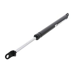
Gas Springs - Mounting Orientation Free Type (FGSS22150A)


- Volume Discount
Gas spring that is a swivel type in mounting direction. You can choose the stroke from 50 to 300 mm.
(i)Caution
- Since the speed cannot be adjusted with gas springs, please select an air cylinder when speed adjustment is required. When confirming the actual reaction force of gas spring, please purchase at the minimum unit and select accordingly.
- Please check the content on our website as the PDF does not contain the most up-to-date information.
Part Number
Configured Part Number is shown.
FGSS22150A

[ M ] Material:
Cylinders : STKM11A
(STKM Hollows for Machine Structural Use)
Rod : S20C
Gas : Nitrogen Gas (N2)
[ S ] Surface Treatment:
Cylinders : Baked-on Finish (Black matt)
Rod : Hard Chrome Plating
Specifications
| Part Number |
| FGSS15050A |

Alterations

■ Dust boot installation modification Compatible with FGSS/FGS No.18□□□ to 22□□□
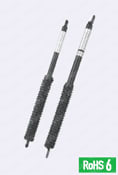 | Additional work Code DBT 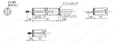 Mounting flange FGS22250 to FGS22360 FGSS18100A to FGSS22300B mounting part FGS18120 to FGS18200 mounting part [M] Material: Tarpaulin |
|
| Compatible gas spring | Additional charge \ Base unit price | ||||
| Type | Compatible No. | stroke | |||
| ~100 | ~200 | ~300 | ~360 | ||
| FGSS | 18□□□ | - | - | ||
| 22□□□ | - | ||||
| FGS | 18□□□ | - | - | - | |
| 22□□□ | - | - | |||
[ ! ] Even at the maximum stroke,
please use within the range where there is a 10 mm margin from the stroke end.
Part Number
CAD Data download and 3D preview are not available because the part number has not yet been determined.
- *In order to open the CAD Data download and 3D preview screen, the part number must be fixed.
- Please confirm the part number from "Specification / Dimension"on the left side, and then perform the CAD Data Download / 3D Preview operation.
| Part Number |
|---|
| FGSS22150A |
| Part Number | Standard Unit Price | Minimum order quantity | Volume Discount | Days to Ship | RoHS | Min. Length Lmin (mm) | Gas Reaction Force 1 (at Max. Length - 10mm Stroke) (N) | Stroke (mm) | Rod Dia. (B) (Ø) | Cylinder Dia. (A) (Ø) | Max. Length Lmax (mm) |
|---|---|---|---|---|---|---|---|---|---|---|---|
MYR 102.29 | 1 Piece(s) | Available | 2 Day(s) or more | 10 | 376 | 196 | 150 | 10 | 22 | 526 |
Loading...
About Gas Spring
A compressed gas (nitrogen gas: non-flammable) is sealed in a closed cylinder,
the reaction force of this gas is used as a spring. Despite its compact size,
this gas spring can provide a small spring constant with a large initial load,
making it suitable for a wide range of applications, including various types of machinery,
furniture, automobiles, and office automation equipment.
· In spite of its size and weight, large spring (reaction) force can be obtained.
· Spring (reaction) force is almost constant throughout its stroke.
· Can be designed to meet specific requirements for a wide range of applications.
· Features of mounting orientation free type gas spring
1. Nitrogen gas (non-combustible) is sealed in gas chamber C with a free moving piston
intervening, and gas reaction force is used as a spring.
2. Gas chamber C has a constant reaction force in extending direction since it pressurizes
oil chamber AB. Therefore the size of the reaction force depends on the inner pressure of
gas chamber C.
3. When rod moves from the predetermined position, oil in chamber AB moves through
orifice hole of the piston.
4. The rod volume change in the cylinder is adjusted by the change of gas chamber C.
5. Usable at any angle of 360°.

Gas Springs – Mounting Orientation Free Type
· Pay attention to the temperature of gas springs during use. Do not store for a prolonged duration. Otherwise, the seal will deteriorate prematurely, causing a decrease in reaction force.
(Product temperature range: FGS, FGSS, GSSF, GSKSF: -20°C to 60°C / HFGSS: -20°C to 80°C / FRGSS: -30°C to 80°C. Some products have different temperature ranges. Please check the relevant page.)
· Gas reaction forces have slight tolerances that vary depending on the product and may change with temperature.
· Reaction force may decrease depending on the operating environment and times of use. Please replace it when it cannot reach the necessary reaction force.
· Do not store or use in environments where the rod may rust, or in chemical atmosphere. Furthermore, do not paint the gas spring.
· Do not damage the cylinders and rods. If rods are wrapped with tape or plastic string, adhesives or fibers are stuck to its surface and then, into the inside, resulting in gas / oil leakage.
Be sure to see if there is no rust, scratches, adhesives or foreign objects on the rod before use.
· Do not apply forces like bending load and torsion to the cylinder and rod. Receiving load only with gas springs results in unbalanced load, which causes early deterioration of the seal, abnormal noise, and gas / oil leakage. To ensure proper use, please note the followings:
For Rotary Motion· Increase the strength of the door itself to prevent the gas spring mounting part from tilting.
· Ensure to prevent gaps and looseness on the hinge to remain the rattling-free state.
For Linear Motion
· Install guide rails, etc. to prevent lateral force to the gas spring.
· Use two or more gas springs as necessary to ensure that the force is applied evenly.
· Do not extend the gas spring beyond its maximum length. Even in the maximum stroke (during compression), it must remain about 10 mm away from the stroke end.
Do not extend and compress at high speeds (with 1 m/s or more).
· Use FGS with the cylinder side oriented upward and the rod side oriented downward, so that internal oil protects the rubber seal.
For FGS and FRGSS, do not tilt more than 60 degrees. When it is necessary to temporarily store, do not tilt more than 60 degrees.
· Although there is no restriction in the use angle for the FGSS, HFGSS, GSSF, and GSKSF type, downward use of the rod is recommended.
Selection Supporting Information
1. Calculate the necessary reaction force (Fg) through the following formula, then find out possible part numbers.
| Fg = | W × L2 |
| L3 |
W: Weight of doors, etc.
L2: Horizontal distance between fulcrum (door hinge, etc.,) and the center of gravity
L3: Vertical distance between fulcrum (door hinge, etc.,) and the axis of gas spring
2. Select Fg x 1.1 or more for the gas spring reaction force.
Gas reaction force has a tolerance of about ±15%.3. If required reaction force (F x 1.1) is larger than the reaction force at the maximum length of gas spring
-( ) mm, use 2 or more springs.
4. Reaction forces are designed at 20°C. Reaction forces increase or decrease as the temperature changes.
About Final Selection
· The load may vary depending on door angles or gas spring mounting positions.
Calculate the reaction force moment based on the subject design drawing.
· When the door is stopped in the horizontal position, it is held in place by the gas spring and lifting force.
The required lifting force (Fh) can be determined by considering the balance of the moment
at the center of rotation. The moment can be calculated by multiplying the load by the length of the arm.
 Fg: Necessary reaction force (at maximum length)
Fh: Lifting force
W: Weight of doors, etc.
L1: Distance between the fulcrum and the operating position
L2: Horizontal distance between fulcrum (door hinge, etc.,) and the center of gravity
L3: Vertical distance between fulcrum (door hinge, etc.,) and the axis of gas spring
θ: The angle between the perpendicular line from the fulcrum and the axis of the gas spring
n: Number of gas springs used

Gas reaction force at the maximum length
- 10 (5) mm and the maximum length (Lmax.)
- (S) mm are listed in this catalog.
Gas reaction force generally changes proportionately.
If the gas reaction force on a certain stroke is required,
connect the 2 points with a straight line as shown in
the table below and read the value on the stroke to conjecture.

[ ! ] f = Internal Sliding Resistance (Theoretical Value x 0.1)
Calculating the moment when the door is fully open
| Fh= | (W×L2−n×Fg×cos(𝜃)×L3) |
| L1 |
· Adjust the lifting force (Fh) determined using the above formula to be in the -2 to -7 kgf range.
When this lifting force (Fh) is positive, the door will descend due to its weight if the gas reaction
force is not applied. A latch or other fastening is required to hold the door open. Conversely,
if the negative value of the operating force is large, a large force is required to close the door.

· As with the fully open state, the lifting force (Fh) when the gas spring is installed and closed is calculated using
| Fh= | (W×L2−n×Fg×cos(𝜃)×L3) |
| L1 |
· Adjust Fh force to be in the 2 to 7 kgf range. When this lifting force (Fh) is negative, the door will open
using only the force of the gas spring. For this reason, the door must be secured with a stopper,
magnet, etc.
· The lifting force varies depending on the distance between the gas spring and the fulcrum and the gas
reaction force depending on whether the door is open or closed, but the calculation method is the same
whether the door is fully open or fully closed.
· At some point during the opening and closing of the door, its weight moment around the fulcrum and
the gas spring's gas reaction force moment will balance out, resulting in a lifting force of 0 (zero).
If the sign of the lifting force is the same (positive, negative) when the door is fully open and when
fully closed, no balance point exists.
· Please review the calculation results above, and select the best option by repeating the calculation process,
changing the installation point or gas spring, etc. exists.

Basic Information
| Gas Spring Type | Free Mounting Direction | Material Rod | S20C | Material Cylinder | STKM11A (Carbon Steel Hollows for Machine Structural Use) |
|---|---|---|---|---|---|
| Operating Direction Range | 360° | Operating Temperature(°C) | -20::60 | Type | Gas Springs |
Please check the type/dimensions/specifications of the part FGSS22150A in the Gas Springs - Mounting Orientation Free Type series.

Specification/Dimensions
-
type
- FGSS
-
Min. Length Lmin(mm)
-
Gas Reaction Force 1 (at Max. Length - 10mm Stroke)(N)
-
Stroke(mm)
-
Rod Dia. (B)(Ø)
-
Cylinder Dia. (A)(Ø)
-
Max. Length Lmax(mm)
-
CAD
- 2D
- 3D
Days to Ship
-
- All
- 1 Day(s) or Less
- 2 Day(s) or Less
- 4 Day(s) or Less
Specify Alterations
- The specifications and dimensions of some parts may not be fully covered. For exact details, refer to manufacturer catalogs .
Products like this...
| Part Number |
|---|
| FGSS15080A |
| FGSS15080B |
| FGSS15090A |
| FGSS22150B |
| FGSS22150C |
| FGSS22180A |
| Part Number | Standard Unit Price | Minimum order quantity | Volume Discount | Days to Ship | RoHS | Min. Length Lmin (mm) | Gas Reaction Force 1 (at Max. Length - 10mm Stroke) (N) | Stroke (mm) | Rod Dia. (B) (Ø) | Cylinder Dia. (A) (Ø) | Max. Length Lmax (mm) |
|---|---|---|---|---|---|---|---|---|---|---|---|
MYR 90.46 | 1 Piece(s) | Available | 1 Day(s) or more | - | 250 | 49 | 80 | 7 | 15 | 330 | |
MYR 90.46 | 1 Piece(s) | Available | 1 Day(s) or more | - | 250 | 98 | 80 | 7 | 15 | 330 | |
MYR 90.46 | 1 Piece(s) | Available | 4 Day(s) or more | - | 270 | 49 | 90 | 7 | 15 | 360 | |
MYR 102.29 | 1 Piece(s) | Available | 2 Day(s) or more | 10 | 376 | 294 | 150 | 10 | 22 | 526 | |
MYR 102.29 | 1 Piece(s) | Available | 1 Day(s) or more | 10 | 376 | 392 | 150 | 10 | 22 | 526 | |
MYR 112.05 | 1 Piece(s) | Available | 2 Day(s) or more | 10 | 430 | 196 | 180 | 10 | 22 | 610 |
Additional Products in this Category
- Stainless Steel Gas Springs
- Gas Springs - Mounting Orientation Limited Type
- Gas Springs - Mounting Orientation Free, GSKSF Type
- KPF Series (Free Piston)
- Damper
- Air Damper (B-481 / Aluminum)
- Gas spring Gas reaction force specified type
- Gas spring GSKF series (mounting orientation free type)
Complementary Products
-
 Rotary Shafts D Tolerance h9 (Cold-drawn) / h7 (Ground) / g6 (Ground) - One End Stepped and Threaded, One End Tapped
MISUMI Days to Ship : 5 Day(s) or more
-
 Cantilever Shafts - Threaded with Retaining Ring Groove - Standard
MISUMI Days to Ship : 5 Day(s) or more


Customers Who Viewed This Item Also Viewed
-
 Gas Springs - Mounting Orientation Limited Type
MISUMI
Standard Price : MYR 89.95-
Days to Ship : 1 Day(s) or more
-
 Mounting Brackets for Gas Springs
MISUMI
Standard Price : MYR 28.27-
Days to Ship : 1 Day(s) or more
-

-
 Gas Springs/Mounting Brackets for Gas Springs - Mounting Orientation Limited Type
MISUMI
Standard Price : MYR 27.19
Days to Ship : 2 Day(s) or more
-
-
 Aluminum Hinges / Aluminum Hinges for Different Extrusion Sizes
MISUMI
Standard Price : MYR 19.85-
Days to Ship : 1 Day(s) or more
-
-
 Free Joint (Bracket) for Gas Damper (Bracket, B-461-BRACK, Stainless Steel)
TAKIGEN
Standard Price : MYR 26.35-
Days to Ship : 2 Day(s) or more
-

-

-
-


Tech Support
- Factory Automation, Electronics, Tools, & MRO (Maintenance, Repair and Operations)
- Tel:(60) 3 7890 6399
- 9:00am - 6:00pm (Monday - Friday)
9:00am - 1:00pm (Saturday) - Technical Inquiry
- Credit Card
- Bank Transfer



Social Media
MISUMI Contact
Copyright © MISUMI Corporation All Rights Reserved.
How can we improve?
How can we improve?
While we are not able to respond directly to comments submitted in this form, the information will be reviewed for future improvement.
Customer Privacy Policy
Thank you for your cooperation.
While we are not able to respond directly to comments submitted in this form, the information will be reviewed for future improvement.
Please use the inquiry form.
Customer Privacy Policy